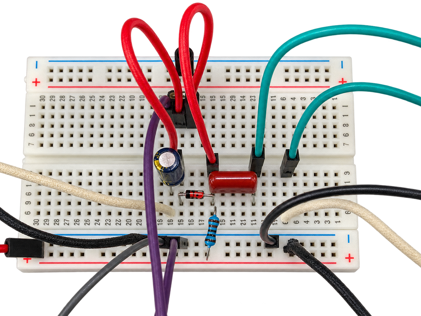
Breadboard fuzz. I built a fuzz circuit on a breadboard and tested its output through a guitar amp. This is the working setup, with its wires, components, and sound out in the open.
Bench test · 12 sec the whole setup,
follow the build ↓
01 / Reference + simulation
A footprint-sized Bazz Fuss reference schematic. MPSA14 transistor, BAT41 collector-to-base diode, 10 kilohm collector resistor, 470 nanofarad input capacitor, 100 nanofarad output capacitor, and 100 kilohm volume potentiometer. These reference values and connections have not been verified against the photographed breadboard.
DC supply
+9 V
R1
10 kΩ
IN
C1
470 nF
input coupling
D1
BAT41
Q1
MPSA14
Darlington
C2
100 nF
output coupling
VR1 · volume
100 kΩ
OUT
GND
leave the
Breadboard + circuit reference
Photo Overlay Diagram
Tap the build to compare
R1 10 kΩ
C1 470 nF
C2 100 nF
D1 BAT41
Q1 MPSA14
VR1 100 kΩ · volume a different way to see it
A circuit assembled on a solderless breadboard, with components and jumper wires left accessible.
Bazz Fuss reference values · schematic layout, not a hole-by-hole wiring map.
03 / Plan the layout
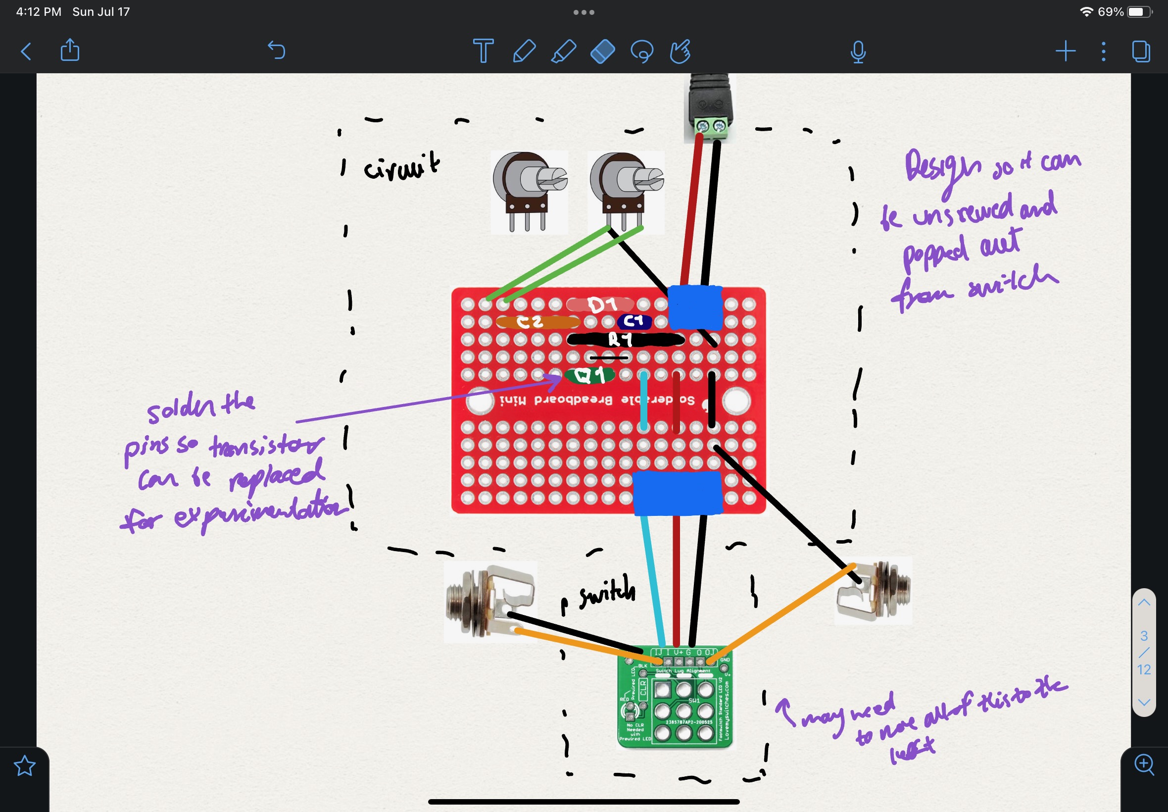
03–04 / Layout to prototype
From loose wires to a soldered board.
Layout notes Open full size ↗ think about access
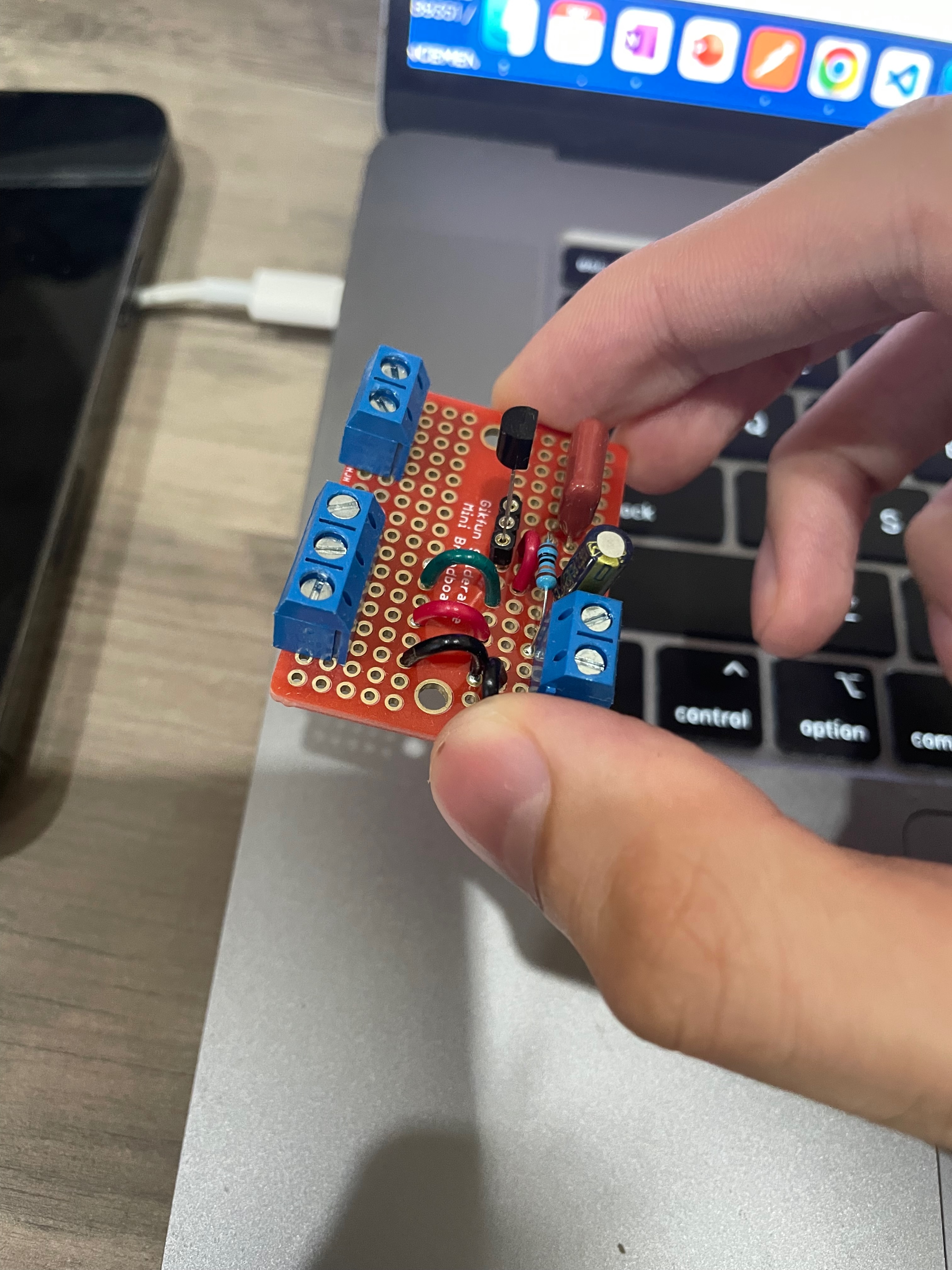
Soldered prototype leave room to swap
A build you can inspect, adjust, and keep working on.